


Light being refracted by a spherical glass container full of water. Roger Bacon, 13th century

Lens for LSST, a planned sky surveying telescope
عدسة عدسية – Lenticular lens – Wikipedia
من ويكيبيديا
عدسة عدسية عبارة عن مجموعة من العدسات المكبرة ، مصممة بحيث يتم تكبير الصور المختلفة عند عرضها من زوايا مختلفة قليلاً.[1][فشل التحقق – انظر المناقشة] المثال الأكثر شيوعًا هو العدسات المستخدمة في طباعة عدسية، حيث تُستخدم التكنولوجيا لإعطاء وهم بالعمق ، أو لعمل صور تبدو وكأنها تتغير أو تتحرك أثناء عرض الصورة من زوايا مختلفة.
طباعة عدسية
المقال الرئيسي: طباعة عدسية
الطباعة العدسية هي عملية متعددة الخطوات تتكون من إنشاء صورة عدسية من صورتين موجودتين على الأقل ، ودمجها مع عدسة عدسية. يمكن استخدام هذه العملية لإنشاء إطارات مختلفة من حيوية (لتأثير الحركة) ، معادلة الطبقات المختلفة بزيادات مختلفة (من أجل a ثلاثي الأبعاد تأثير) ، أو ببساطة لإظهار مجموعة من الصور البديلة التي قد تبدو وكأنها تتحول إلى بعضها البعض.
العدسات التصحيحية
تستخدم العدسات العدسية في بعض الأحيان العدسات التصحيحية لتحسين الرؤية. أ عدسة ثنائية البؤرة يمكن اعتباره مثالًا بسيطًا.
عدسي النظارات تم استخدام العدسات لتصحيح التطرف مد البصر (طول النظر) ، وهي حالة تنشأ غالبًا عن إعتمام عدسة العين متى الجراحة زرع العدسة غير ممكن. للحد من السماكة والوزن الكبيرين اللذين تتطلبهما مثل هذه العدسات عالية الطاقة ، قوة العدسة تتركز في مساحة صغيرة في المركز. في المظهر ، غالبًا ما توصف هذه العدسة بأنها تشبه أ بيض مقلي: نصف كروي فوق سطح مستو. يمتلك السطح المسطح أو “العدسة الحاملة” طاقة قليلة أو معدومة وهي موجودة فقط لملء بقية إطار النظارات ولاحتواء أو “حمل” الجزء العدسي من العدسة. يبلغ قطر هذا الجزء عادةً 40 مم (1.6 بوصة) ولكنه قد يكون أصغر ، بحيث يصل إلى 20 مم (0.79 بوصة) ، بقدرات عالية بدرجة كافية. تُستخدم هذه العدسات عمومًا للتصحيحات الزائدة (المفرطة) عند حوالي 12 ديوبتر أو أعلى. نوع مماثل من عدسات النظارات هو قرص عضلي، يطلق عليها أحيانًا عدسة سالبة عدسية ، وتستخدم للإشارة إلى صور سلبية عالية جدًا (قصر النظر) التصحيحات. أكثر جمالية عدسة شبه كروية يتم تركيب التصميمات في بعض الأحيان.[2] يمكن وضع فيلم مصنوع من عدسات أسطوانية مصبوب في ركيزة بلاستيكية كما هو موضح في الصورة أعلاه ، على داخل الزجاج القياسي لتصحيح شفع. يتم تطبيق الفيلم عادة على العين مع التحكم الجيد في اتجاه العضلات. عادة ما ينتج ضعف الرؤية (المعروف أيضًا باسم الرؤية المزدوجة) عن شلل العصب القحفي السادس الذي يمنع التحكم الكامل في العضلات التي تتحكم في اتجاه العين. ويتم تحديد هذه الأفلام في عدد درجات التصحيح المطلوبة حيث كلما زادت الدرجة ، كلما زاد التصحيح التوجيهي المطلوب.
شاشات عدسية
كثيرا ما تستخدم الشاشات ذات السطح العدسي المصبوب مع تلفزيون الإسقاط أنظمة. في هذه الحالة ، يكون الغرض من العدسات هو تركيز المزيد من الضوء في شعاع أفقي والسماح بقدر أقل من الضوء بالهروب أعلى وأسفل طائرة من المشاهد. بهذه الطريقة ، يزداد السطوع الظاهر للصورة.
يمكن أيضًا وصف شاشات الإسقاط الأمامية العادية بأنها عدسية. في هذه الحالة ، بدلاً من العدسات الشفافة ، تكون الأشكال المتكونة عبارة عن عاكسات منحنية صغيرة.
تلفزيون ثلاثي الأبعاد
اعتبارًا من 2010، قام عدد من الشركات المصنعة بتطوير دقة عالية مجسمة تلقائية تلفزيونات ثلاثية الأبعاد، وذلك باستخدام أنظمة العدسات العدسية لتجنب الحاجة إلى خاص نظارات. واحدة من هؤلاء ، الشركة المصنعة الصينية TCL ، كانت تبيع طراز LCD مقاس 42 بوصة (110 سم) – TD-42F – في الصين مقابل حوالي 20000 دولار أمريكي.[3]
عمليات الصور المتحركة الملونة العدسية
تم استخدام العدسات العدسية في عمليات الصور المتحركة الملونة المبكرة في عشرينيات القرن الماضي مثل كيلر دوريان النظام و كوداكولور. وقد أتاح ذلك الصور الملونة باستخدام مخزون أفلام أحادية اللون فقط.[4]
زاوية نظر بصمة عدسية
زاوية رؤية الطباعة العدسية هي نطاق الزوايا التي يمكن للمراقب من خلالها رؤية الصورة بأكملها. يتم تحديد ذلك بالزاوية القصوى التي عندها a شعاع يمكن ترك الصورة من خلال العدسة الصحيحة.
زاوية داخل العدسة:
يُظهر الرسم البياني على اليمين باللون الأخضر الشعاع الأكثر تطرفاً داخل العدسة العدسية منكسر بشكل صحيح من العدسة. يترك هذا الشعاع إحدى حواف شريط الصورة (في أسفل اليمين) ويخرج من خلال الحافة المقابلة للعدس المقابل.
تعريفات
هي الزاوية بين الشعاع الأقصى و عادي عند نقطة خروجها من العدسة ،
هي درجة أو عرض كل خلية عدسية ،
هل نصف قطر انحناء من العدس ،
هي سماكة العدسة العدسية
هي سماكة الركيزة الموجودة أسفل السطح المنحني للعدسة ، و
هي العدسة معامل الانكسار.
عملية حسابية

أين


زاوية خارج العدسة
تُعطى الزاوية خارج العدسة بانكسار الشعاع المحدد أعلاه. زاوية المراقبة الكاملة 

أين 

أين 
مثال
فكر في طباعة عدسية بها عدسات ذات 336.65 µ م الملعب ، نصف قطر انحناء 190.5 ميكرومتر ، سمك 457 ميكرومتر ، ومعامل انكسار 1.557 ميكرومتر. زاوية المراقبة الكاملة
المستوى البؤري الخلفي لشبكة عدسية
ال البعد البؤري العدسة من معادلة Lensmaker، والذي يتم تبسيطه في هذه الحالة إلى:
أين 
يقع المستوى البؤري الخلفي على مسافة 

يشير BFD السلبي إلى أن المستوى البؤري يكمن في داخل العدسة.
في معظم الحالات ، يتم تصميم العدسات العدسية بحيث يتطابق المستوى البؤري الخلفي مع المستوى الخلفي للعدسة. الشرط لهذه المصادفة 

تفرض هذه المعادلة علاقة بين سماكة العدسة
مثال
العدسة العدسية في المثال أعلاه لها الطول البؤري 342 ميكرومتر والمسافة البؤرية الخلفية 48 ميكرومتر ، مما يشير إلى أن المستوى البؤري للعدسة يقع 48 ميكرومتر خلف الصورة المطبوعة على ظهر العدسة.


Lens
From Wikipedia
A lens is a transmissive optical device that focuses or disperses a light beam by means of refraction. A simple lens consists of a single piece of transparent material, while a compound lens consists of several simple lenses (elements), usually arranged along a common axis. Lenses are made from materials such as glass or plastic, and are ground and polished or molded to a desired shape. A lens can focus light to form an image, unlike a prism, which refracts light without focusing. Devices that similarly focus or disperse waves and radiation other than visible light are also called lenses, such as microwave lenses, electron lenses, acoustic lenses, or explosive lenses.
Lenses are used in various imaging devices like telescopes, binoculars and cameras. They are also used as visual aids in glasses to correct defects of vision such as myopia and hypermetropia.
History
The word lens comes from lēns , the Latin name of the lentil, because a double-convex lens is lentil-shaped. The lentil plant also gives its name to a geometric figure.[1]
Some scholars argue that the archeological evidence indicates that there was widespread use of lenses in antiquity, spanning several millennia.[2] The so-called Nimrud lens is a rock crystal artifact dated to the 7th century BC which may or may not have been used as a magnifying glass, or a burning glass.[3][4][5] Others have suggested that certain Egyptian hieroglyphs depict “simple glass meniscal lenses”.[6][verification needed]
The oldest certain reference to the use of lenses is from Aristophanes’ play The Clouds (424 BC) mentioning a burning-glass.[7] Pliny the Elder (1st century) confirms that burning-glasses were known in the Roman period.[8] Pliny also has the earliest known reference to the use of a corrective lens when he mentions that Nero was said to watch the gladiatorial games using an emerald (presumably concave to correct for nearsightedness, though the reference is vague).[9] Both Pliny and Seneca the Younger (3 BC–65 AD) described the magnifying effect of a glass globe filled with water.
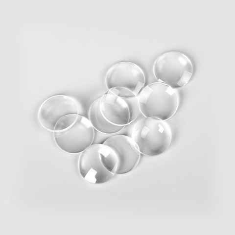
Ptolemy (2nd century) wrote a book on Optics, which however survives only in the Latin translation of an incomplete and very poor Arabic translation. The book was, however, received by medieval scholars in the Islamic world, and commented upon by Ibn Sahl (10th century), who was in turn improved upon by Alhazen (Book of Optics, 11th century). The Arabic translation of Ptolemy’s Optics became available in Latin translation in the 12th century (Eugenius of Palermo 1154). Between the 11th and 13th century “reading stones” were invented. These were primitive plano-convex lenses initially made by cutting a glass sphere in half. The medieval (11th or 12th century) rock crystal Visby lenses may or may not have been intended for use as burning glasses.[10]
Spectacles were invented as an improvement of the “reading stones” of the high medieval period in Northern Italy in the second half of the 13th century.[11] This was the start of the optical industry of grinding and polishing lenses for spectacles, first in Venice and Florence in the late 13th century,[12] and later in the spectacle-making centres in both the Netherlands and Germany.[13] Spectacle makers created improved types of lenses for the correction of vision based more on empirical knowledge gained from observing the effects of the lenses (probably without the knowledge of the rudimentary optical theory of the day).[14][15] The practical development and experimentation with lenses led to the invention of the compound optical microscope around 1595, and the refracting telescope in 1608, both of which appeared in the spectacle-making centres in the Netherlands.[16][17]
Further information: History of the telescope
With the invention of the telescope and microscope there was a great deal of experimentation with lens shapes in the 17th and early 18th centuries by those trying to correct chromatic errors seen in lenses. Opticians tried to construct lenses of varying forms of curvature, wrongly assuming errors arose from defects in the spherical figure of their surfaces.[18] Optical theory on refraction and experimentation was showing no single-element lens could bring all colours to a focus. This led to the invention of the compound achromatic lens by Chester Moore Hall in England in 1733, an invention also claimed by fellow Englishman John Dollond in a 1758 patent.
Construction of simple lenses
Most lenses are spherical lenses: their two surfaces are parts of the surfaces of spheres. Each surface can be convex (bulging outwards from the lens), concave (depressed into the lens), or planar (flat). The line joining the centres of the spheres making up the lens surfaces is called the axis of the lens. Typically the lens axis passes through the physical centre of the lens, because of the way they are manufactured. Lenses may be cut or ground after manufacturing to give them a different shape or size. The lens axis may then not pass through the physical centre of the lens.
Toric or sphero-cylindrical lenses have surfaces with two different radii of curvature in two orthogonal planes. They have a different focal power in different meridians. This forms an astigmatic lens. An example is eyeglass lenses that are used to correct astigmatism in someone’s eye.
Types of simple lenses
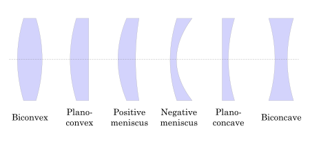
Lenses are classified by the curvature of the two optical surfaces. A lens is biconvex (or double convex, or just convex) if both surfaces are convex. If both surfaces have the same radius of curvature, the lens is equiconvex. A lens with two concave surfaces is biconcave (or just concave). If one of the surfaces is flat, the lens is plano-convex or plano-concave depending on the curvature of the other surface. A lens with one convex and one concave side is convex-concave or meniscus. It is this type of lens that is most commonly used in corrective lenses.
If the lens is biconvex or plano-convex, a collimated beam of light passing through the lens converges to a spot (a focus) behind the lens. In this case, the lens is called a positive or converging lens. For a thin lens in air, the distance from the lens to the spot is the focal length of the lens, which is commonly represented by f in diagrams and equations. An extended hemispherical lens is a special type of plano-convex lens, in which the lens’s curved surface is a full hemisphere and the lens is much thicker than the radius of curvature.
If the lens is biconcave or plano-concave, a collimated beam of light passing through the lens is diverged (spread); the lens is thus called a negative or diverging lens. The beam, after passing through the lens, appears to emanate from a particular point on the axis in front of the lens. For a thin lens in air, the distance from this point to the lens is the focal length, though it is negative with respect to the focal length of a converging lens.
Convex-concave (meniscus) lenses can be either positive or negative, depending on the relative curvatures of the two surfaces. A negative meniscus lens has a steeper concave surface and is thinner at the centre than at the periphery. Conversely, a positive meniscus lens has a steeper convex surface and is thicker at the centre than at the periphery. An ideal thin lens with two surfaces of equal curvature would have zero optical power, meaning that it would neither converge nor diverge light. All real lenses have nonzero thickness, however, which makes a real lens with identical curved surfaces slightly positive. To obtain exactly zero optical power, a meniscus lens must have slightly unequal curvatures to account for the effect of the lens’ thickness.
Lensmaker’s equation[edit]
The position of the focus of a spherical lens depends on the radii of curvature of the two facets.
The focal length of a lens in air can be calculated from the lensmaker’s equation:[19]{\displaystyle {\frac {1}{f}}=(n-1)\left[{\frac {1}{R_{1}}}-{\frac {1}{R_{2}}}+{\frac {(n-1)d}{nR_{1}R_{2}}}\right],}
![{\frac {1}{f}}=(n-1)\left[{\frac {1}{R_{1}}}-{\frac {1}{R_{2}}}+{\frac {(n-1)d}{nR_{1}R_{2}}}\right],](https://wikimedia.org/api/rest_v1/media/math/render/svg/26fb54977c7f965da063dcaded08258c3377f1d9)
where{\displaystyle f}


The focal length f is positive for converging lenses, and negative for diverging lenses. The reciprocal of the focal length, 1/f, is the optical power of the lens. If the focal length is in metres, this gives the optical power in dioptres (inverse metres).
Lenses have the same focal length when light travels from the back to the front as when light goes from the front to the back. Other properties of the lens, such as the aberrations are not the same in both directions.
Sign convention for radii of curvature R1 and R2[edit]
Main article: Radius of curvature (optics)
The signs of the lens’ radii of curvature indicate whether the corresponding surfaces are convex or concave. The sign convention used to represent this varies, but in this article a positive R indicates a surface’s center of curvature is further along in the direction of the ray travel (right, in the accompanying diagrams), while negative R means that rays reaching the surface have already passed the center of curvature. Consequently, for external lens surfaces as diagrammed above, R1 > 0 and R2 < 0 indicate convex surfaces (used to converge light in a positive lens), while R1 < 0 and R2 > 0 indicate concave surfaces. The reciprocal of the radius of curvature is called the curvature. A flat surface has zero curvature, and its radius of curvature is infinity.
Thin lens approximation[edit]
If d is small compared to R1 and R2, then the thin lens approximation can be made. For a lens in air, f is then given by{\displaystyle {\frac {1}{f}}\approx \left(n-1\right)\left[{\frac {1}{R_{1}}}-{\frac {1}{R_{2}}}\right].}![{\frac {1}{f}}\approx \left(n-1\right)\left[{\frac {1}{R_{1}}}-{\frac {1}{R_{2}}}\right].](https://wikimedia.org/api/rest_v1/media/math/render/svg/c633e7b574392e54107881cd2e697e0ba9a68877)
Imaging properties[edit]
As mentioned above, a positive or converging lens in air focuses a collimated beam travelling along the lens axis to a spot (known as the focal point) at a distance f from the lens. Conversely, a point source of light placed at the focal point is converted into a collimated beam by the lens. These two cases are examples of image formation in lenses. In the former case, an object at an infinite distance (as represented by a collimated beam of waves) is focused to an image at the focal point of the lens. In the latter, an object at the focal length distance from the lens is imaged at infinity. The plane perpendicular to the lens axis situated at a distance f from the lens is called the focal plane.
If the distances from the object to the lens and from the lens to the image are S1 and S2 respectively, for a lens of negligible thickness (thin lens), in air, the distances are related by the thin lens formula:[21][22][23]{\displaystyle {\frac {1}{S_{1}}}+{\frac {1}{S_{2}}}={\frac {1}{f}}.}

This can also be put into the “Newtonian” form:{\displaystyle x_{1}x_{2}=f^{2},\!}
where {\displaystyle x_{1}=S_{1}-f}

Therefore, if an object is placed at a distance S1 > f from a positive lens of focal length f, we will find an image distance S2 according to this formula. If a screen is placed at a distance S2 on the opposite side of the lens, an image is formed on it. This sort of image, which can be projected onto a screen or image sensor, is known as a real image. Alternatively, this real image can also be viewed by the human eyes, as shown in the picture below (with the caption “A convex lens (f ≪ S1) forming a real, inverted image …”).Virtual image formation using a positive lens as a magnifying glass.[25]
This is the principle of the camera, and of the human eye. The focusing adjustment of a camera adjusts S2, as using an image distance different from that required by this formula produces a defocused (fuzzy) image for an object at a distance of S1 from the camera. Put another way, modifying S2 causes objects at a different S1 to come into perfect focus.
In some cases S2 is negative, indicating that the image is formed on the opposite side of the lens from where those rays are being considered. Since the diverging light rays emanating from the lens never come into focus, and those rays are not physically present at the point where they appear to form an image, this is called a virtual image. Unlike real images, a virtual image cannot be projected on a screen, but appears to an observer looking through the lens as if it were a real object at the location of that virtual image. Likewise, it appears to a subsequent lens as if it were an object at that location, so that second lens could again focus that light into a real image, S1 then being measured from the virtual image location behind the first lens to the second lens. This is exactly what the eye does when looking through a magnifying glass. The magnifying glass creates a (magnified) virtual image behind the magnifying glass, but those rays are then re-imaged by the lens of the eye to create a real image on the retina.

A negative lens produces a demagnified virtual image.

A Barlow lens (B) reimages a virtual object (focus of red ray path) into a magnified real image (green rays at focus)
Using a positive lens of focal length f, a virtual image results when S1 < f, the lens thus being used as a magnifying glass (rather than if S1 >> f as for a camera). Using a negative lens (f < 0) with a real object (S1 > 0) can only produce a virtual image (S2 < 0), according to the above formula. It is also possible for the object distance S1 to be negative, in which case the lens sees a so-called virtual object. This happens when the lens is inserted into a converging beam (being focused by a previous lens) before the location of its real image. In that case even a negative lens can project a real image, as is done by a Barlow lens.

Real image of a lamp is projected onto a screen (inverted). Reflections of the lamp from both surfaces of the biconvex lens are visible.
_and_upside-down_image.jpg)
A convex lens (f ≪ S1) forming a real, inverted image (as the image formed by the objective lens of a telescope or binoculars) rather than the upright, virtual image as seen in a magnifying glass(f > S1) . This real image may also be viewed when put on a screen.
For a thin lens, the distances S1 and S2 are measured from the object and image to the position of the lens, as described above. When the thickness of the lens is not much smaller than S1 and S2 or there are multiple lens elements (a compound lens), one must instead measure from the object and image to the principal planes of the lens. If distances S1 or S2 pass through a medium other than air or vacuum a more complicated analysis is required.
Magnification[edit]
The linear magnification of an imaging system using a single lens is given by{\displaystyle M=-{\frac {S_{2}}{S_{1}}}={\frac {f}{f-S_{1}}},}

where M is the magnification factor defined as the ratio of the size of an image compared to the size of the object. The sign convention here dictates that if M is negative, as it is for real images, the image is upside-down with respect to the object. For virtual images M is positive, so the image is upright.
This magnification formula provides two easy ways to distinguish converging (f > 0) and diverging (f < 0) lenses: For an object very close to the lens (0 < S1 < |f|), a converging lens would form a magnified (bigger) virtual image, whereas a diverging lens would form a demagnified (smaller) image; For an object very far from the lens (S1 > |f| > 0), a converging lens would form an inverted image, whereas a diverging lens would form an upright image.
Linear magnification M is not always the most useful measure of magnifying power. For instance, when characterizing a visual telescope or binoculars that produce only a virtual image, one would be more concerned with the angular magnification—which expresses how much larger a distant object appears through the telescope compared to the naked eye. In the case of a camera one would quote the plate scale, which compares the apparent (angular) size of a distant object to the size of the real image produced at the focus. The plate scale is the reciprocal of the focal length of the camera lens; lenses are categorized as long-focus lenses or wide-angle lenses according to their focal lengths.
Using an inappropriate measurement of magnification can be formally correct but yield a meaningless number. For instance, using a magnifying glass of 5 cm focal length, held 20 cm from the eye and 5 cm from the object, produces a virtual image at infinity of infinite linear size: M = ∞. But the angular magnification is 5, meaning that the object appears 5 times larger to the eye than without the lens. When taking a picture of the moon using a camera with a 50 mm lens, one is not concerned with the linear magnification M ≈ −50 mm / 380000 km = −1.3×10⁻¹⁰. Rather, the plate scale of the camera is about 1°/mm, from which one can conclude that the 0.5 mm image on the film corresponds to an angular size of the moon seen from earth of about 0.5°.
In the extreme case where an object is an infinite distance away, S1 = ∞, S2 = f and M = −f/∞= 0, indicating that the object would be imaged to a single point in the focal plane. In fact, the diameter of the projected spot is not actually zero, since diffraction places a lower limit on the size of the point spread function. This is called the diffraction limit.Images of black letters in a thin convex lens of focal length f are shown in red. Selected rays are shown for letters E, I and K in blue, green and orange, respectively. Note that E (at 2f) has an equal-size, real and inverted image; I (at f) has its image at infinity; and K (at f/2) has a double-size, virtual and upright image.
Aberrations[edit]
| vte Optical aberration |
|---|
| Defocus Tilt Spherical aberration Astigmatism Coma Distortion Petzval field curvature Chromatic aberration |
Main article: Optical aberration
Lenses do not form perfect images, and a lens always introduces some degree of distortion or aberration that makes the image an imperfect replica of the object. Careful design of the lens system for a particular application minimizes the aberration. Several types of aberration affect image quality, including spherical aberration, coma, and chromatic aberration.
Spherical aberration[edit]
Main article: Spherical aberration
Spherical aberration occurs because spherical surfaces are not the ideal shape for a lens, but are by far the simplest shape to which glass can be ground and polished, and so are often used. Spherical aberration causes beams parallel to, but distant from, the lens axis to be focused in a slightly different place than beams close to the axis. This manifests itself as a blurring of the image. Spherical aberration can be minimised with normal lens shapes by carefully choosing the surface curvatures for a particular application. For instance, a plano-convex lens, which is used to focus a collimated beam, produces a sharper focal spot when used with the convex side towards the beam source.

Coma[edit]
Main article: Coma (optics)
Coma, or comatic aberration, derives its name from the comet-like appearance of the aberrated image. Coma occurs when an object off the optical axis of the lens is imaged, where rays pass through the lens at an angle to the axis θ. Rays that pass through the centre of a lens of focal length f are focused at a point with distance f tan θ from the axis. Rays passing through the outer margins of the lens are focused at different points, either further from the axis (positive coma) or closer to the axis (negative coma). In general, a bundle of parallel rays passing through the lens at a fixed distance from the centre of the lens are focused to a ring-shaped image in the focal plane, known as a comatic circle. The sum of all these circles results in a V-shaped or comet-like flare. As with spherical aberration, coma can be minimised (and in some cases eliminated) by choosing the curvature of the two lens surfaces to match the application. Lenses in which both spherical aberration and coma are minimised are called bestform lenses.

Chromatic aberration[edit]
Main article: Chromatic aberration
Chromatic aberration is caused by the dispersion of the lens material—the variation of its refractive index, n, with the wavelength of light. Since, from the formulae above, f is dependent upon n, it follows that light of different wavelengths is focused to different positions. Chromatic aberration of a lens is seen as fringes of colour around the image. It can be minimised by using an achromatic doublet (or achromat) in which two materials with differing dispersion are bonded together to form a single lens. This reduces the amount of chromatic aberration over a certain range of wavelengths, though it does not produce perfect correction. The use of achromats was an important step in the development of the optical microscope. An apochromat is a lens or lens system with even better chromatic aberration correction, combined with improved spherical aberration correction. Apochromats are much more expensive than achromats.
Different lens materials may also be used to minimise chromatic aberration, such as specialised coatings or lenses made from the crystal fluorite. This naturally occurring substance has the highest known Abbe number, indicating that the material has low dispersion.


Other types of aberration[edit]
Other kinds of aberration include field curvature, barrel and pincushion distortion, and astigmatism.
Aperture diffraction[edit]
Even if a lens is designed to minimize or eliminate the aberrations described above, the image quality is still limited by the diffraction of light passing through the lens’ finite aperture. A diffraction-limited lens is one in which aberrations have been reduced to the point where the image quality is primarily limited by diffraction under the design conditions.
Compound lenses[edit]
See also: Photographic lens, Doublet (lens), Triplet lens, and Achromatic lens
Simple lenses are subject to the optical aberrations discussed above. In many cases these aberrations can be compensated for to a great extent by using a combination of simple lenses with complementary aberrations. A compound lens is a collection of simple lenses of different shapes and made of materials of different refractive indices, arranged one after the other with a common axis.
The simplest case is where lenses are placed in contact: if the lenses of focal lengths f1 and f2 are “thin“, the combined focal length f of the lenses is given by{\displaystyle {\frac {1}{f}}={\frac {1}{f_{1}}}+{\frac {1}{f_{2}}}.}

Since 1/f is the power of a lens, it can be seen that the powers of thin lenses in contact are additive.
If two thin lenses are separated in air by some distance d, the focal length for the combined system is given by{\displaystyle {\frac {1}{f}}={\frac {1}{f_{1}}}+{\frac {1}{f_{2}}}-{\frac {d}{f_{1}f_{2}}}.}

The distance from the front focal point of the combined lenses to the first lens is called the front focal length (FFL):{\displaystyle {\text{FFL}}={\frac {f_{1}(f_{2}-d)}{(f_{1}+f_{2})-d}}.}
Similarly, the distance from the second lens to the rear focal point of the combined system is the back focal length (BFL):{\displaystyle {\text{BFL}}={\frac {f_{2}(d-f_{1})}{d-(f_{1}+f_{2})}}.}

As d tends to zero, the focal lengths tend to the value of f given for thin lenses in contact.
If the separation distance is equal to the sum of the focal lengths (d = f1 + f2), the FFL and BFL are infinite. This corresponds to a pair of lenses that transform a parallel (collimated) beam into another collimated beam. This type of system is called an afocal system, since it produces no net convergence or divergence of the beam. Two lenses at this separation form the simplest type of optical telescope. Although the system does not alter the divergence of a collimated beam, it does alter the width of the beam. The magnification of such a telescope is given by{\displaystyle M=-{\frac {f_{2}}{f_{1}}},}

which is the ratio of the output beam width to the input beam width. Note the sign convention: a telescope with two convex lenses (f1 > 0, f2 > 0) produces a negative magnification, indicating an inverted image. A convex plus a concave lens (f1 > 0 > f2) produces a positive magnification and the image is upright. For further information on simple optical telescopes, see Refracting telescope § Refracting telescope designs.
Non spherical types[edit]
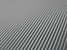
Cylindrical lenses have curvature along only one axis. They are used to focus light into a line, or to convert the elliptical light from a laser diode into a round beam. They are also used in motion picture anamorphic lenses.
Aspheric lenses have at least one surface that is neither spherical nor cylindrical. The more complicated shapes allow such lenses to form images with less aberration than standard simple lenses, but they are more difficult and expensive to produce. These were formerly complex to make and often extremely expensive, but advances in technology have greatly reduced the manufacturing cost for such lenses.Close-up view of a flat Fresnel lens.
A Fresnel lens has its optical surface broken up into narrow rings, allowing the lens to be much thinner and lighter than conventional lenses. Durable Fresnel lenses can be molded from plastic and are inexpensive.
Lenticular lenses are arrays of microlenses that are used in lenticular printing to make images that have an illusion of depth or that change when viewed from different angles.
Bifocal lens has two or more, or a graduated, focal lengths ground into the lens.
A gradient index lens has flat optical surfaces, but has a radial or axial variation in index of refraction that causes light passing through the lens to be focused.
An axicon has a conical optical surface. It images a point source into a line along the optic axis, or transforms a laser beam into a ring.[27]
Diffractive optical elements can function as lenses.
Superlenses are made from negative index metamaterials and claim to produce images at spatial resolutions exceeding the diffraction limit.[28] The first superlenses were made in 2004 using such a metamaterial for microwaves.[28] Improved versions have been made by other researchers.[29][30] As of 2014 the superlens has not yet been demonstrated at visible or near-infrared wavelengths.[31]
A prototype flat ultrathin lens, with no curvature has been developed.[32]
Uses[edit]
A single convex lens mounted in a frame with a handle or stand is a magnifying glass.
Lenses are used as prosthetics for the correction of refractive errors such as myopia, hypermetropia, presbyopia, and astigmatism. (See corrective lens, contact lens, eyeglasses.) Most lenses used for other purposes have strict axial symmetry; eyeglass lenses are only approximately symmetric. They are usually shaped to fit in a roughly oval, not circular, frame; the optical centres are placed over the eyeballs; their curvature may not be axially symmetric to correct for astigmatism. Sunglasses’ lenses are designed to attenuate light; sunglass lenses that also correct visual impairments can be custom made.
Other uses are in imaging systems such as monoculars, binoculars, telescopes, microscopes, cameras and projectors. Some of these instruments produce a virtual image when applied to the human eye; others produce a real image that can be captured on photographic film or an optical sensor, or can be viewed on a screen. In these devices lenses are sometimes paired up with curved mirrors to make a catadioptric system where the lens’s spherical aberration corrects the opposite aberration in the mirror (such as Schmidt and meniscus correctors).
Convex lenses produce an image of an object at infinity at their focus; if the sun is imaged, much of the visible and infrared light incident on the lens is concentrated into the small image. A large lens creates enough intensity to burn a flammable object at the focal point. Since ignition can be achieved even with a poorly made lens, lenses have been used as burning-glasses for at least 2400 years.[7] A modern application is the use of relatively large lenses to concentrate solar energy on relatively small photovoltaic cells, harvesting more energy without the need to use larger and more expensive cells.
Radio astronomy and radar systems often use dielectric lenses, commonly called a lens antenna to refract electromagnetic radiation into a collector antenna.
Lenses can become scratched and abraded. Abrasion-resistant coatings are available to help control this.[33]
See also[edit]
- Anti-fogging treatment of optical surfaces
- Back focal plane
- Bokeh
- Cardinal point (optics)
- Caustic (optics)
- Eyepiece
- F-number
- Gravitational lens
- Lens (anatomy)
- List of lens designs
- Numerical aperture
- Optical coatings
- Optical lens design
- Photochromic lens
- Prism (optics)
- Ray tracing
- Ray transfer matrix analysis